FPGA Control for Robotics
Our 16-299 Course Project analyzes how we can use FPGAs to control a robot.
🔧 FPGA-Based Control System
By Ayush Garg and Alan Wang
16-299: Introduction to Feedback Control Systems, Instructor: Professor Christopher Atkeson
Welcome to our course project page! This project explores how Field Programmable Gate Arrays (FPGAs) can be used to implement high-frequency control systems and image processing algorithms directly in hardware using SystemVerilog.
After several weeks of design, simulation, and hardware implementation, we have successfully completed and demonstrated the project.
📽 Final Demo Video
Watch our completed video walkthrough, which explains:
- What FPGAs are and why they’re ideal for control systems
- The full architecture and SystemVerilog implementation
- A live working demo of our FPGA-based system in action
🎥 Prefer a direct link? Watch the full demo on Google Drive
💡 Why FPGAs for Control?
FPGAs offer key advantages for robotics and control applications:
- 🕒 Real-Time Speed: No OS or software stack — pure hardware-level execution
- 🧠 Parallelism: Execute multiple control steps simultaneously
- ⚙️ Customization: Hardware tailored exactly to the control problem
We implemented a PID-style feedback controller and a simple image-processing pipeline fully on the FPGA fabric.
✅ What We Accomplished
- ✅ Designed a custom controller datapath in SystemVerilog
- ✅ Built a UART interface for PC communication (with fallback to GPIO)
- ✅ Synthesized and deployed to FPGA hardware
- ✅ Captured a successful real-time control demo on video
- ✅ Documented everything for reproducibility
🛠 Reproducing the Project
Want to build on or replicate our work? Follow the steps below:
1. Clone the Repo
2. Using an FPGA-accessible computer (found in Hamerschlag Hall ECE Labs), run and synthesize the SystemVerilog code and program this onto the FPGA.
3. Turn on the robot and program its Arduino with the repository’s Arduino code from this Repo using a personal computer (laptop or separate desktop).
4. Run the Python script on a camera-accessible computer (separate from the computer used in Step 2) to communicate between the camera, the FPGA, and the robot.
5. Use a piece of paper with distinctly different colors near the center to let the camera images detect color movement in.
6. Run the transmit/receive command from the FPGA-accessible computer to allow the FPGA to transmit and receive commands.
7. Using the paper with a distinct color, move it left and right with the camera, and you can see the robot reflect these motions physically!
🧠 How to Improve Upon Our Results
While our project successfully demonstrated FPGA-based control and image processing, there are several ways to build on this work listed below:
- Extend the image processing pipeline, e.g., edge detection or basic filters
- Scale the design to control multiple devices in parallel
- Create a GUI or web interface for live tuning and visualization
- Use a higher-capacity FPGA to explore more complex or multi-threaded designs
These extensions would increase the project’s robustness, usability, and real-world applicability.
We also had some limitations to our project. Due to licensing issues, we were forced to utilize 2 separate computers on top of the FPGA and Arduino. This increased the latency of our system significantly. Future work can aim to improve upon these limitations.
🤖 Equipment Specifications
FPGA: Xilinx Spartan-7 XC7S50-CSGA324
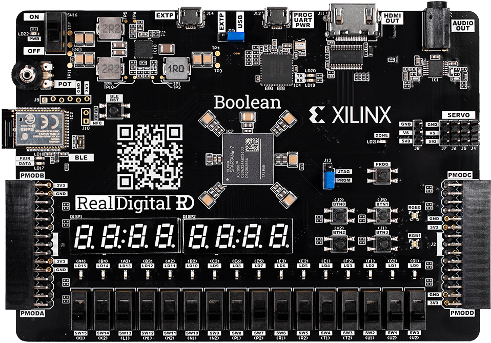
Fig 1. Image of our FPGA
Robot: 4WD 60mm Mecanum Wheel Arduino Robot Kit
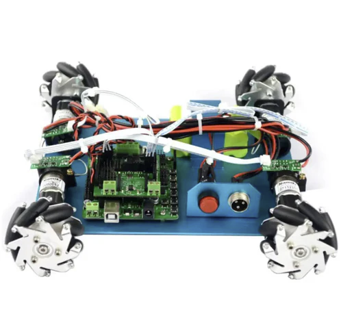
Fig 2. Image of our robot
🙏 Acknowledgments
Thanks to the CMU ECE Department for hardware/toolchain support and to our Professor, Christopher Atkeson, and our Teaching Assistant, Krishna Suresh, in 16-299: Introduction to Feedback Control Systems for their guidance.